PressTip construction
Much of this work is published in this paper and my PhD thesis.This section outlines the development of the PressTip sensor, an electrical multi-modal sensor that works at a much lower resolution than an optical tactile sensor. We discuss various prototypes and the final result which comes in the form of two designs. A tip that matches the size of the optical sensor, and a larger robotic foot. We finally look at initial processing of this sensor and discuss some of the hardware limitations. We initially experimented with force-sensitive resistors embedded in a silicone body to create low-resolution skin sensors with soft compliance. Our first prototype used pre-made force sensors infused in a silicone block. Therefore allowing us to read different pressures across a surface area. The flat surfaces of the sensors had to be bent to fit into the silicone, which lead to inconsistent readings. Furthermore, the silicone would not fuse to the pressure sensor strips, which meant some were not physically constrained enough. We attempted to update the design in a larger surface area of contact body, with only sensors fused within high contact areas. This was the sides of the feet.
The prototypes did demonstrate reactional readings to stimuli showing us that infused force sensors showed further promise. However, aside from the inconsistency issues, there were a large number of wires in the prototypes. When these wires were moved it could disrupt signals coming from the sensor. This added too much noise, therefore we developed these prototypes into a PCB that combined force and vibration sensing.
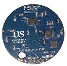
We developed the PressTip, a novel sensor combining multiple aspects of electrical tactile sensing. By using different combinations of the accelerometer, piezoelectric and pressure signals available from the PressTip, we can effectively provide different kinds of electrical sensors in our comparative study. The PressTip has a vibration-sensitive piezoelectric sensor, 3-axis accelerometers and an array of 15 force sensors on the bottom side of the PCB. Piezoelectric sensors detect vibrations and mechanical strain using the piezoresistive effect, where a material’s electrical resistance changes under mechanical stress. These sensors typically feature a piezoresistive material (often silicon) bonded to a flexible substrate. Vibrations deform the material, altering its resistance, which is then converted into a proportional electrical signal.
Accelerometers measure vibration by detecting changes in acceleration. They contain a mass suspended by a spring inside a casing. Vibration causes the mass to move, deforming the spring and generating an electrical signal proportional to the acceleration. Due to their compact size and high sensitivity, accelerometers are widely used across electronics, machinery, and vehicles.
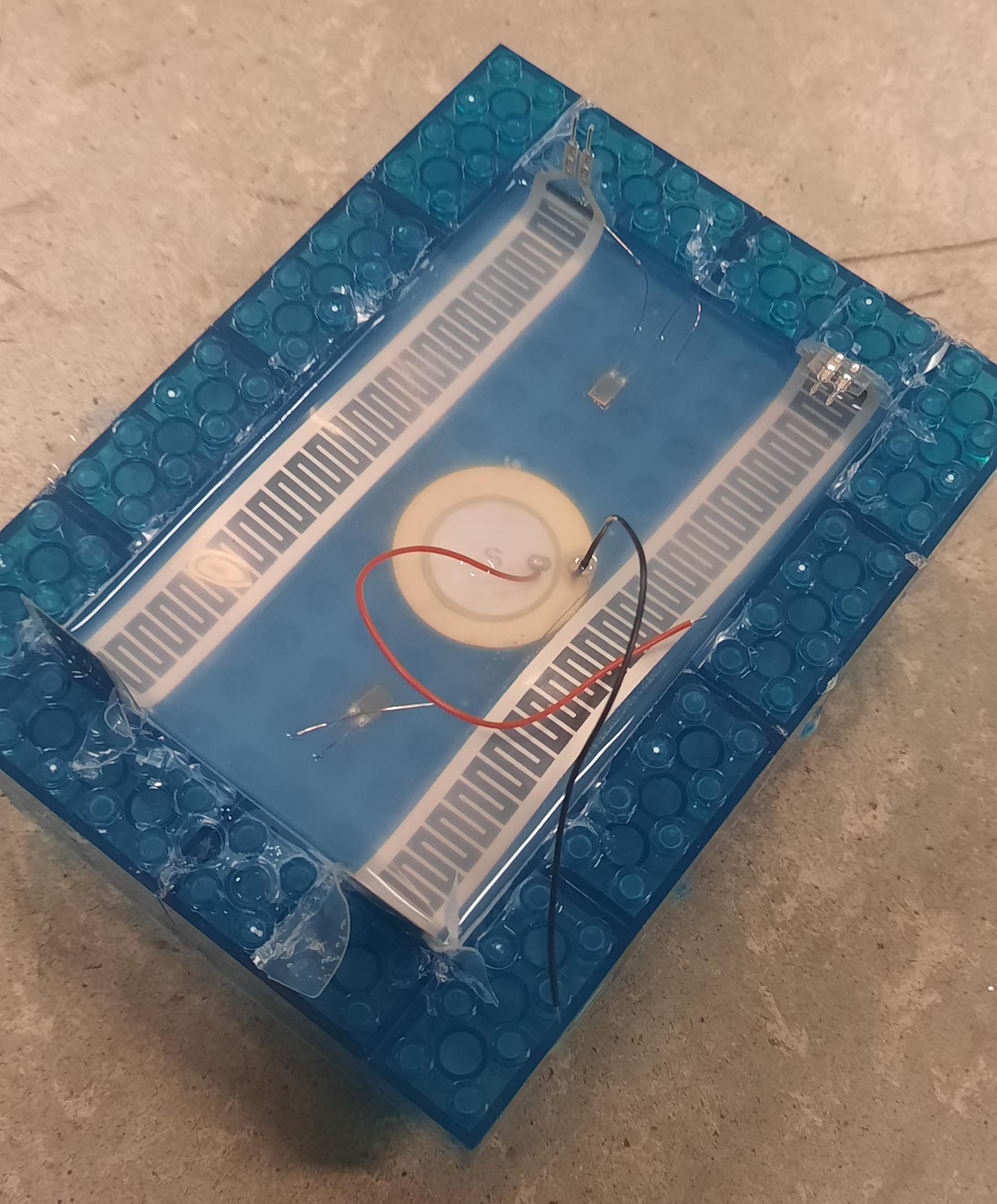
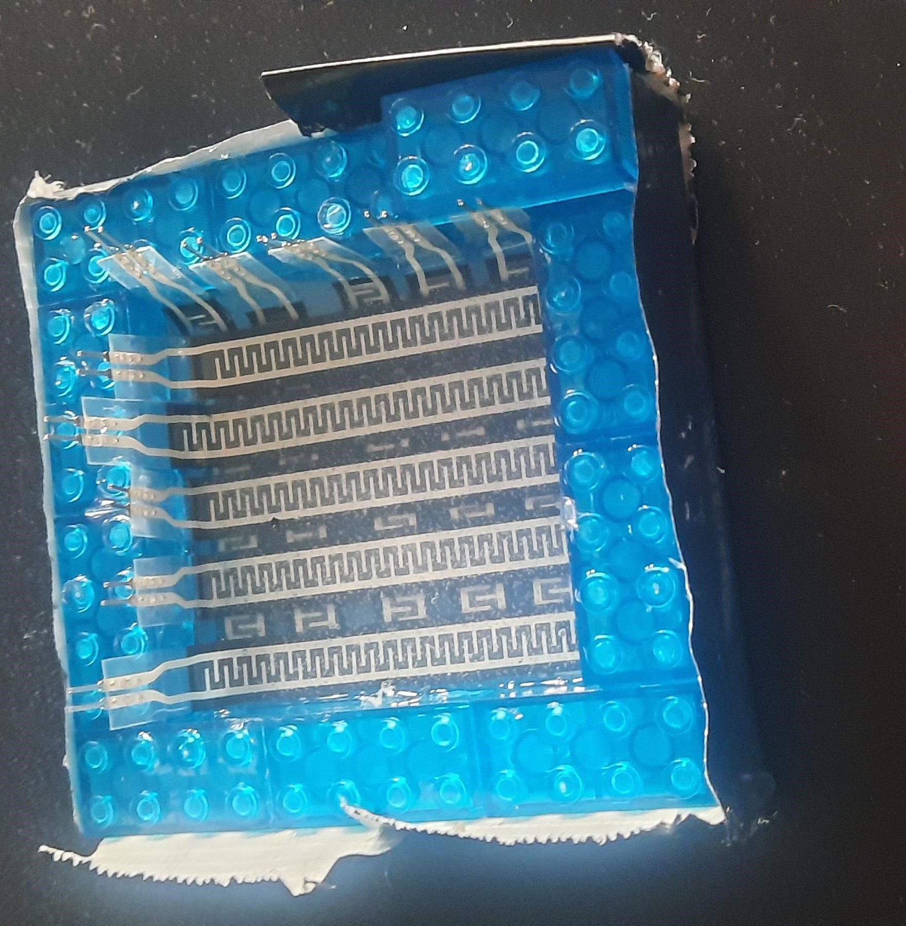
The force sensors were constructed using a conductive material (velostat) which changes resistance based on force, these are the black squares seen in figure. Previous work showed that these force sensors are useful for a range of classification tasks, including under-foot edge detection. However, after performing preliminary experiments, we discovered that the information from the force sensor array was not suited to the texture classification task addressed in later chapters. Overlaid is a silicone pad taken from a pack of door pads. It was the perfect fit and very cheap.
.jpeg)
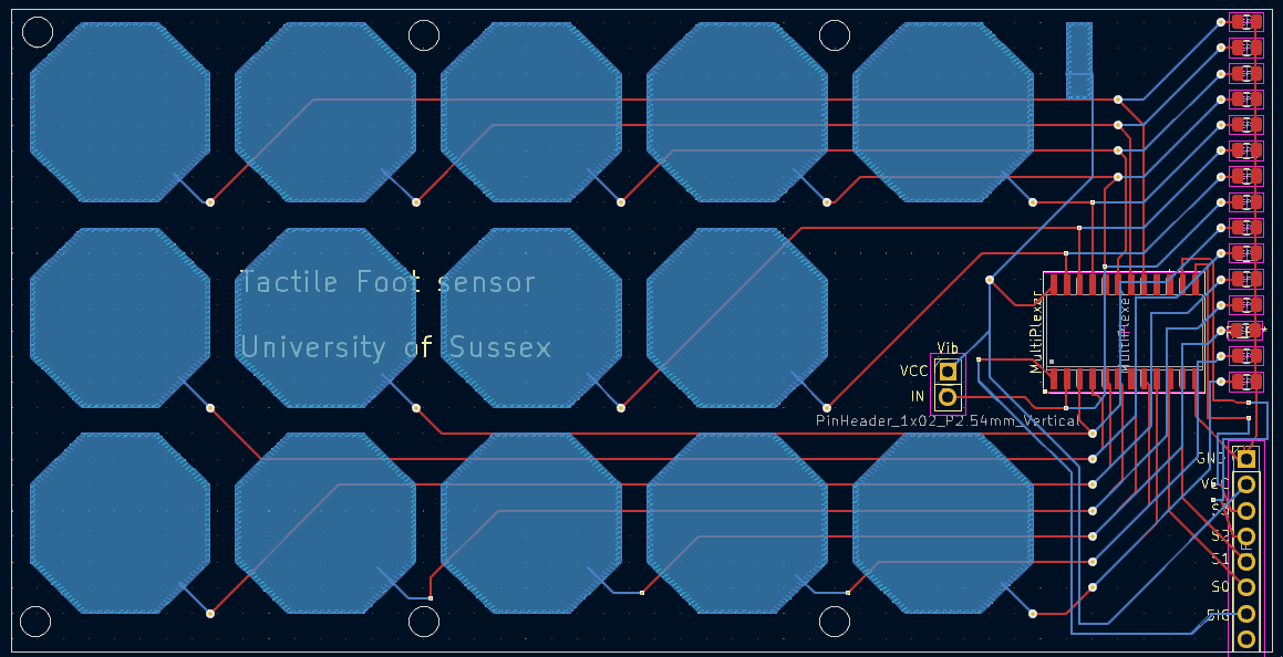
Along with the rounded PressTip, we constructed a larger foot sensor. We designed and printed a PCB with 14 tactile pads. The tactile pads were approximately 15mm X 15mm split by a thin gap vertically through the middle. One side of the pad is connected to the positive supply of the board. The sensor we present in this paper is on a hard base to cover the foot of a simple bipedal robot.
Limitations of this sensor is the size and I2C buses involved. Each presstip has two ADS7830I working on different I2C buses. These buses can have their channels changed using two binary address inputs to the ADS7830I, thus 4 on one device. This adds a constraint on how many physical pads we could have across a sensor. To go to a higher resolution (more pads) we would need to deploy more sensors on one board. Assuming that the sensors can all fit on the board, this means we can only have a total of 32 pads. But is this higher resolution required? Can we use lower resolutions and still be able to infer information about the robots state. Even for the larger tactile foot that uses a digital selection method for analogue reading (CD4067), we are limited to a number of pins. it still requires four digital pins to select the analogue channel. This is not a significant issue if you are using an Arduino Mega with 54 digital pins and 15 analogue pins, however it still increases the amount of wires going to feet, causing more complexity