
Texture classification
Much of this work is published in this paper and my PhD thesis.Contents
Rig Construction
A 3 degrees of freedom rig (x-axis, y-axis, z-axis), of dimensions 300mm by 300mm by 150mm, was constructed to move a sensor around a 3D environment. This rig was used to gather texture data by stroking the sensor along 1.5mm straight lines in 100 different directions along evenly spaced radii of a semicircle centred on the original touching point. The sensor moved across fixed-down samples from the texture set. Recordings were gathered at various contact forces, using touching point forces of 0.0785 – 0.0824N, 1.9031 – 1.9228N, 3.0039 – 3.0235N and 4.336 – 4.367N. The dataset consists of 3000 items gathered over 15 textures. Each dataset item contains multiple sensor readings concatenated over the time that the sensor is in contact with the surface (approximately 10 seconds).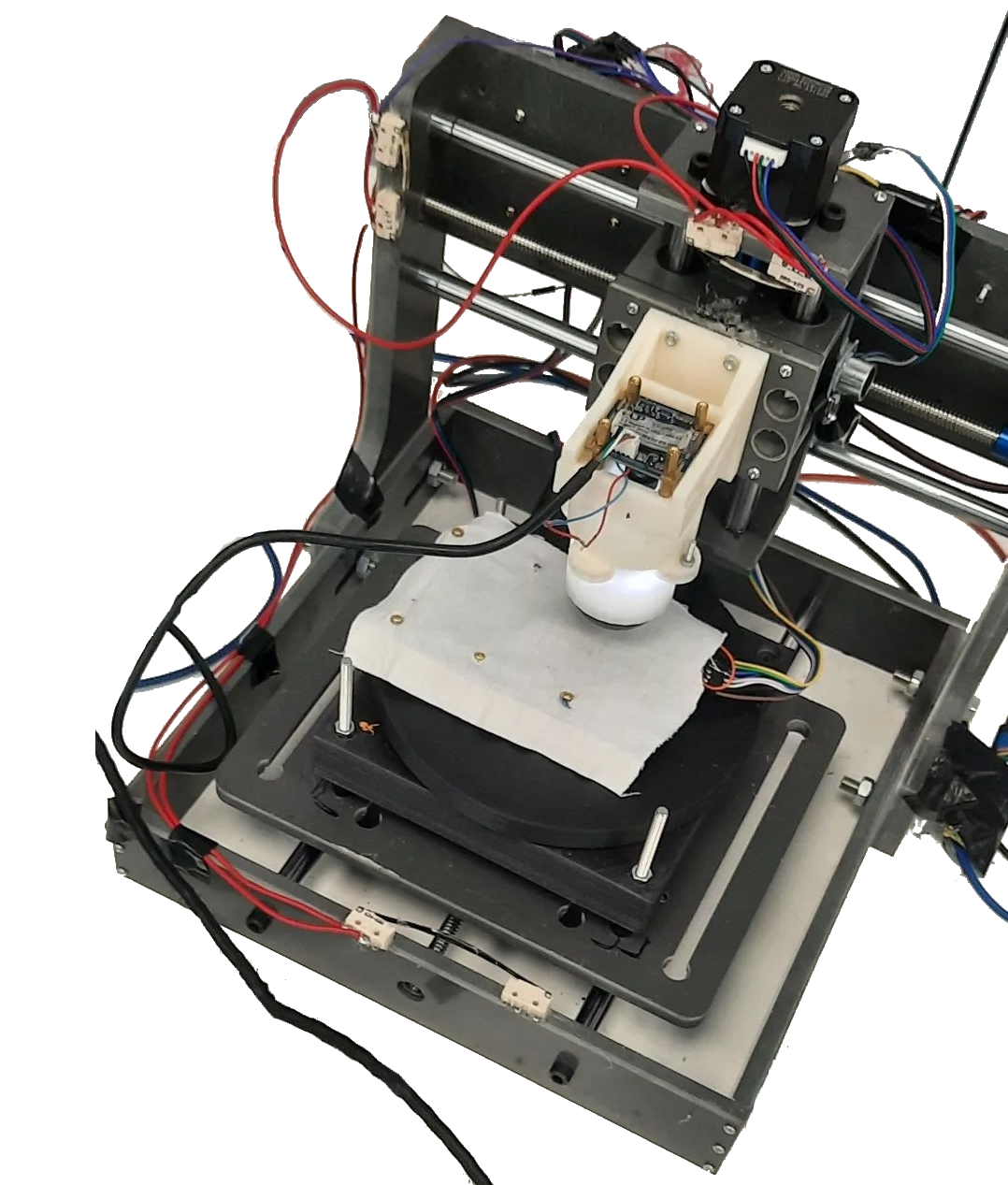
Moving the sensor across varying vectors shows the sensor's ability to classify the different textures with linear stroking movements, this is the most common way of gathering textural datasets. We also investigated how the sensor-classifier pairs performed on sensations they were not trained on. To do this, we collected a non-linear movement dataset by moving the sensor in circular movements of increasing radii (1cm, 1.75cm, 2.5cm) while increasing the contact force by approximately 17 grams on each iteration. We refer to this as the non-linear dataset.
Dataset
Perhaps understandably, most papers on tactile sensing for texture classification have used textured materials that are easily accessible, and to date no standard texture set has been created. Past texture sets are often of different sizes which hampers comparability because, as shown in section, some texture classifiers perform well when distinguishing between small numbers of textures but degrade sharply as the number of classes increase. As established current datasets tend to use items that appear in the labs of the researchers. Often these include some form of carpet, hard materials and fabrics. Our texture dataset was designed to try and include commonalities between previous sets and to represent a range of material properties that a walking robot may come into contact with, such as indoors or flat outdoors surfaces. These included soft/hard bodies, coarse/smooth surfaces and surfaces with raised aspects.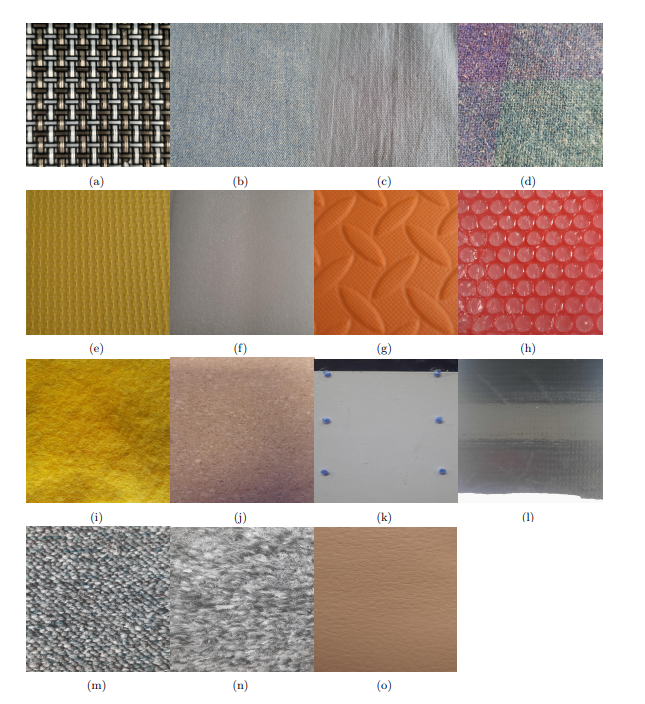
Classification
The results of the comparative texture classification experiments are shown in Table 1 for the various sensor–classifier combinations. It is clear from the table that the optical sensors have much higher accuracy across all classifier types compared to the electrical sensors. However, the electrical sensor combining the accelerometers and piezoelectric sensor offers good accuracy when using an LSTM classifier.
The TacTip employing the new marker morphology performs slightly worse than with the original marker morphology, but is still very accurate. Overall, the best performing sensor is the silicone-filled TacTip, particularly in combination with CNN or LSTM classifiers. While SVM classifiers performed well, they took much longer to train than the other methods.
| Sensor | Classifier | Average Test Accuracy | Average Train Accuracy | Std Test | Max Test |
|---|---|---|---|---|---|
| TT Sil | SVM | 99.96% | 100% | 0.0005 | 100% |
| TT Sil | RFC | 99.9% | 99.98% | 0.025 | 100% |
| TT Sil | CNN | 99.97% | 99.99% | 0 | 99.99% |
| TT Sil | LSTM | 98.1% | 99.1% | 0.018 | 99.9% |
| TT NM | CNN | 89.25% | 90.31% | 2.7 | 94.2% |
| TT NM | LSTM | 95.71% | 96.28% | 0.027 | 99.2% |
| TT PP | RFC | 98.44% | 100% | 0.59 | 99.33% |
| TT PP | SVM | 27.01% | 30.22% | 3.71 | 33.33% |
| TT PP | LSTM | 84.12% | 84.5% | 0.031 | 90.15% |
| TT PP | ANN | 86.16% | 86.5% | 0.026 | 90.48% |
| PT P | SVM | 70% | 70.4% | 0.01 | 71.6% |
| PT A | SVM | 44.75% | 51.1% | 0.025 | 49.1% |
| PT A&P | SVM | 55.45% | 57.8% | 0.03 | 63.8% |
| PT P | RFC | 78.7% | 99.96% | 0.014 | 76.6% |
| PT A | RFC | 62.31% | 100% | 0.02 | 65.6% |
| PT A&P | RFC | 89.6% | 100% | 0.01 | 99.2% |
| PT P | ANN | 66.5% | 66.5% | 0.768 | 67.5% |
| PT A | ANN | 39.57% | 43.94% | 0.759 | 41% |
| PT A&P | ANN | 65.59% | 64.84% | 1.101 | 66.5% |
| PT P | LSTM | 77.37% | 85.03% | 0.67 | 78.6% |
| PT A | LSTM | 38.53% | 42.1% | 2.6 | 42% |
| PT A&P | LSTM | 85.5% | 90% | 0.67 | 86.5% |
Friction Prediction
Initially, we used a range of regression models (Linear, Ridge, Logistic) but found that the Random Forest classifier significantly outperformed the other regression models. Therefore, we only proceeded with the results of Ridge and Random Forest, which performed better than the Linear and Logistic models.
Friction detection model performance was calculated using the mean squared error (MSE) between predicted and true values, with the mean calculated over all textures in the dataset. Although there is more noise in the voltage readings of the electrical sensors, the Random Forest regression model handled this well.
Table 1 displays the results, showing a smaller error from the optical sensor. However, the relative performance of the electrical sensors is good and better than for the texture classification task. The TacTip values are more closely clustered around the line of best fit. Although the electrical sensor readings are noisier and more widely spread, their regression model produced a close match to the actual values. The results shown in Table 2 are for the clear-silicone TacTip and for various configurations of the electrical sensor (which also has a silicone tip).
The Random Forest Regression classifier was found to be one of the quickest to train and highest performing for friction prediction across both sensors. We performed a comparison to evaluate how the different classifiers performed for the task of friction prediction using mean squared error as the metric. The same models were compared for both the electrical and optical sensors, where appropriate for the data type.
The LSTM and CNN classifiers both used hidden layers of 350 nodes. The neural models had one output node and were trained with the Adam optimizer with a learning rate of 0.001. The results are shown in Table 1. The Random Forest was the highest performing model.
| Model | Sensor | Test MSE | Train MSE |
|---|---|---|---|
| Ridge Regression | Optical | 0.0002 | 0.0000 |
| Ridge Regression | Electrical | 0.0238 | 0.0255 |
| CNN | Optical | 0.0412 | 0.0366 |
| LSTM | Optical | 0.0416 | 0.0368 |
| LSTM | Electrical | 0.0368 | 0.0361 |
| Random Forest | Electrical | 0.0030 | 0.0003 |
| Random Forest | Optical | 0.0002 | 0.0000 |
| Sensor | Regression Model | Min MSE | Train MSE Average |
|---|---|---|---|
| Piez | RFR | 0.022 | 0.024 |
| Acc | RFR | 0.019 | 0.021 |
| Acc & Piez | RFR | 0.018 | 0.021 |
| TacTip | RFR | 0.0043 | 0.0049 |
Morphology Experiments
Each image was 110 X 120 pixels over 20 frames, till we cut this down to 4 frames each after hyper-parameter sweeps to find the minimum length to still maintain accuracy. The video shows movement of the TacTip sensor over various directions along 1.5 mm straight lines in 100 different directions. Each direction had evenly spaced radii of a semicircle centred on the original touching point. The rig used three-axis of stepper motors of dimensions 300mm by 300mm by 150mm to allow direction and force to be applied to the sensor across each surface. The forces used were of 0.0785 – 0.0824N, 1.9031 – 1.9228N, 3.0039 – 3.0235N and 4.336 – 4.367N pushed directly onto the texture with the sensor facing downwards so the tip of the soft body would be in contact first.
The new marker skins were attached to the rig setup and used to gather the same dataset as previous experiments. We apply Sobel filters and reduce the images by mean scaling. All the preprocessing steps and model parameters matched that of all previous experiments}. We chose the CNN model due to its success in previous experiments. We used molds with holes, groves and smooth to make a range of tips. Then we coloured in patterns with white paint.
| Morphology | Test Accuracy | Train Accuracy | Std |
|---|---|---|---|
| A | 97.15% | 98.07% | 0.009 |
| B | 99.98% | 99.99% | 0.00 |
| C | 98.23% | 98.5% | 0.01 |
| D | 97.48% | 97.78% | 0.0095 |
| Standard TacTip | 99.97% | 99.99% | 0.00 |
| E | 89.25% | 90.31% | 2.7 |
| No Markers | 99.94% | 99.99% | 0.003 |
Despite having no markers, the no marker design performed at a much higher accuracy than the alternative morphologies. All the designs had high accuracy. When we looked at the sobel-filtered images we noticed there were glare marks on the surface of the gel. These LED markers moved differently dependent on the force on the sensor. These were clearly standing in for the absence of markers. In summary of the morphology experiments, the size of optical markers can indeed impact how the accuracy performs at lower resolutions. This was only evaluated on our task for texture classification, however more work in the area of object and edge recognition would further enhance the study on how pattern shape could help reduce the resolution of tactile images. This work can help decrease the computational costs of this technology. The novel work in morphology changes for classification could be enhanced by using more procedurally generated morphology to explore a wider range of designs. Our focus has been texture classification, rather than edge detection, though experimentation into more than just texture classification could reveal more about the morphologies pros and cons. The methods discussed such as saliency maps would be very useful to determine which aspects of the morphology are useful for each task.