
OpenEduBot
Posted 25/04/2026
This tutorial makes use of a 2 wheeled light following robot. This is based on the braitenberg vehicle idea, where light following behaviour can come from simple wiring. The speed of a motor is proposrtional to the intensity of the light. If the sensor on the left side is wired to the motor on the right, and sensor on the right is wired to the motor on the left, the robot will move towards light. If it is the other way round, the robot will move away from light. But can we evolve this behaviour?
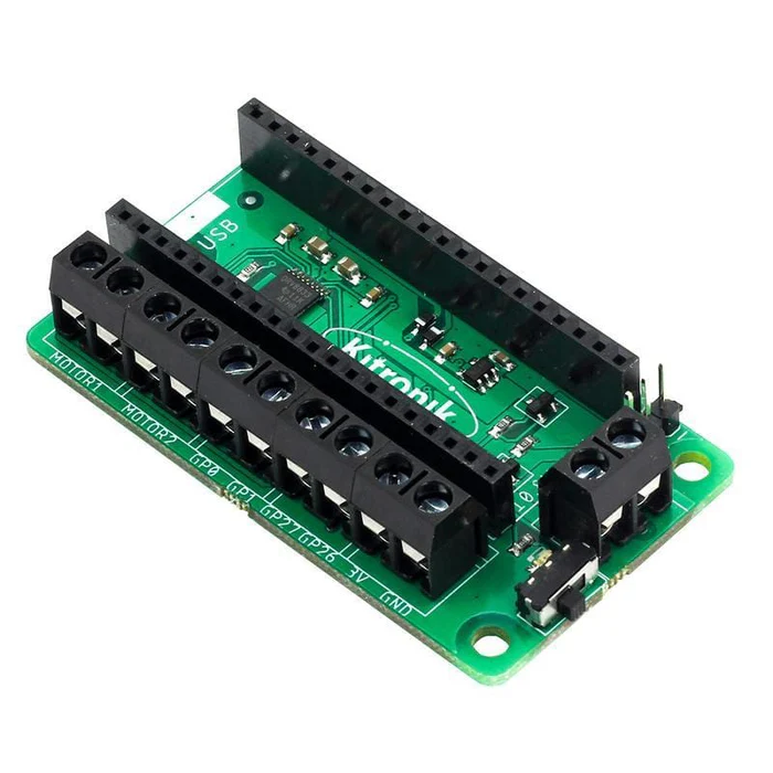
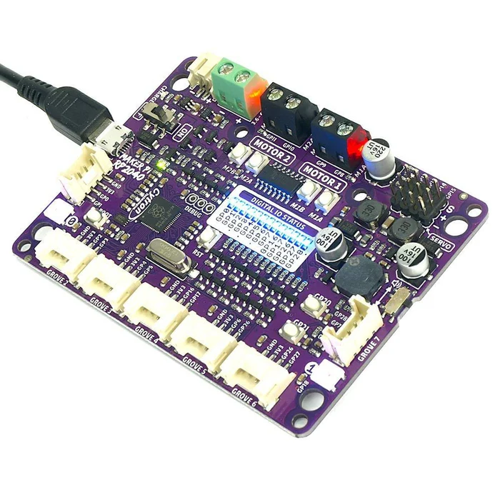
The robot chassis
Build instructions can be found here. The chassis contains two light sensitive resitorys and two dc motors. For a controller it makes use of a Raspberry Pi Pico. The library supports a few different boards (in order) the robotics board, motor driver and cytron board. In the library we refer to the boiard type (in order) as blank or "default", "pico", "pico_1".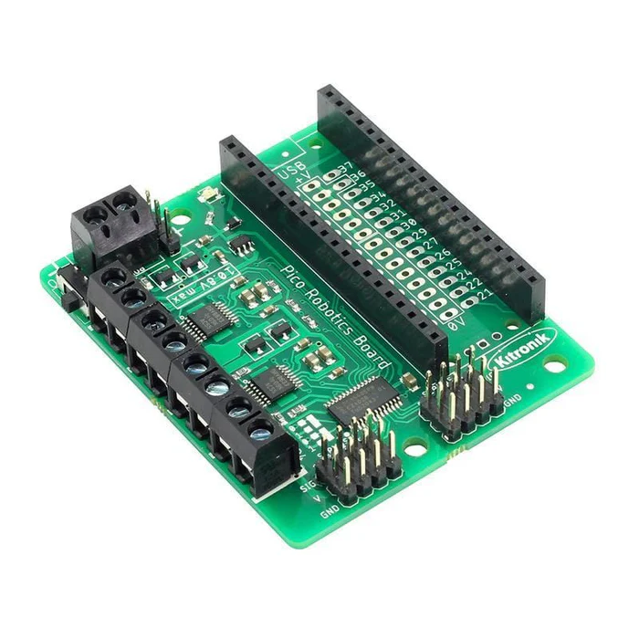
Hardware bugs to watch out for:
- Firstly check the wires are going to the right pins. A common mistake is trying to read from a sensor and it is not in the right pin.
- If a component is very hot, its likely that there is a wring problem, make sure negative and positive are in the right place, and they have not crossed. (Screw mounting points can do this)
- If no power is found in the motors or sensors, its likely the switch on the motor driver is not switched on, or the batteries are empty.
- If the robot is slower or performing worse than before, it means i is low on power. Keep it powered up for best results!
- Make sure to keep the screws tight. This requires readjusting every so often.
The Library
Flashing CircuitPython
We have support for both MicroPython and CircuitPython. This tutorial will be focused on the CircuitPython approach because it contains a variant of numpy. Numpy is useful if we want to recreate networks on the device. Make sure the raspberry pi pico has circuitpython. You can check by connecting the robot via USB to your computer, opening Thonny IDE and seeing what is running on the device. If it gives you the option to install, it means there is no firmware on yet. If it says micropython, you will need to reflash it. If it has circuitpython already, then you are good to go! Flashing the device is quite simple, you disconnect the USB and power, hold down the boot select button on the Pico, and then reconnect to the computer while keeping the button surpressed. Drag and drop the latest circuitpython uf2 file from here onto the device. There are plent of online tutorials on how to do this if you get stuck. Make sure the uf2 is for the right controller. The pico and pico wireless use different uf2. Also the cytron board requires its own as well.The final thing is to make sure you have the right libraries on device. Download the Adafruit library bundle for the device you need. Copy and paste the files/folders from the library bundle download into the /lib directory of the Pico. Only copy the libraries you need. - simpleio - adafruit_motor If you get no module found errors, just look for it in the downloaded folder and copy it over. You will also need to upload the openEduBot Library found here.
Coding
The library is called using the following commands. If you are using the other boards you will need to change the parameter boardtype.
from EduBot_CP import wheelBot

bot = wheelBot()
from EduBot_CP import wheelBot

bot = wheelBot(board_type="pico")
from EduBot_CP import wheelBot

bot = wheelBot(board_type="pico_1")
To get code to run on boot, we must save it as code.py in the main directory of the Pico. This will always run on start up, whether or not the device is connected to a computer or not. As long as it has power.
Moving the robot is quire simple, we select the motor, a direction and a speed. The code below turns one of the motors for full speed for 5 seconds, then reverses the direction of rotation for another 5. It then rotates the other motor in the same way and finally stops moving.
speed_1=100 #100% speed
bot.motorOn(4, "r", speed_1)
time.sleep(5)

bot.motorOn(4, "f", speed_1)
time.sleep(5)

#other motor
bot.motorOn(3, "r", speed_1)
time.sleep(5)

bot.motorOn(3, "f", speed_1)
time.sleep(5)

bot.stop() #stop moving
So moving is fairly simple, lets connect to the light sensors now. We can test that the sensors are working by covering them with our hands and seeing the values printed change. Also using your phone torch. If there is no change then its likely the wiring is wrong. Try GP27 to replace whichever sensor is failing.
from analogio import AnalogIn
sensor_gain=0.5
def get_intensity(pint):
    return (pin.value*3.3) /65536

s1 = AnalogIn(board.GP28)
s2 = AnalogIn(board.GP26)

while True:
    print(get_intensity(s1),get_intensity(s2))
Simulation
Mujoco
Using the OpenEduBot repo you can find a simulated wheelbot using Mujoco. Mujoco is a phsyics simulator developed by Google Deepmind. An example python script is provided in the repo.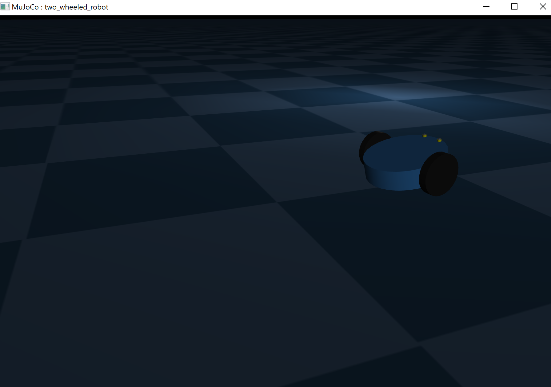
Coding
Firstly we import mujoco, if you have not got mujoco installed simply install it usingpip install mujoco. We then put the directory to the repo directory that stores the wheelbot xml file. The xml file is simply a structured format that provides the physical structure of a robot for mujoco.
import mujoco
import mujoco.viewer
import numpy as np
import time

path="repo/robot/wheelbot.xml"
# Load model
model = mujoco.MjModel.from_xml_path(path)
data = mujoco.MjData(model)
with mujoco.viewer.launch_passive(model,
  data, show_left_ui=False,
  show_right_ui=False) as viewer:
    while viewer.is_running():
        mujoco.mj_forward(model, data)
        mujoco.mj_step(model, data)
        viewer.sync()
A small window with the simualted robot will appear. We make a physics steps using the forward and step functions, and then updated the viewer with viewer.sync().
Like the real wheelbot, we want to be able to read from the light sensors. For this we must simualte them. To being with we must find the light source.
light_id = mujoco.mj_name2id(model,
    mujoco.mjtObj.mjOBJ_LIGHT,
    'top_lamp')
light_pos = model.light_pos[light_id]
Then we can calculate the intensity from the sensor positions to the light source. The following function allows selection of each sensor individually.
def get_virtual_light_intensity(data, site_name):
    # Get current world position of the sensor site
    sensor_pos = data.site(site_name).xpos

    # distance from sensor to light position
    distance = np.linalg.norm(sensor_pos - light_pos)

    # intensity calculation
    return 1.0 / (distance**2 + 0.01)
So we can set the left and right and read one by one:
left_val = get_virtual_light_intensity(data,
    'light_sensor_left')
right_val = get_virtual_light_intensity(data,
    'light_sensor_right')
print(f"Left Sensor: {left_val:.3f},
       Right Sensor: {right_val:.3f}")
Finally, to make changes to the motors we can set the velocities using the ctrl paramter.
data.ctrl[0] = right_val*-100
data.ctrl[1] = left_val*-100
#remember to update the simulation using forward and step!!
mujoco.mj_forward(model, data)
mujoco.mj_step(model, data)
Finally, to get the position of the robot you can use the qpos parameter to get x y and z. Reading this at each timestep and recording it will give you a trajectory that the robot took.
robot_pos = data.qpos[0:3]
Editing the sim
Though we have set up a basic flat environment with a light source, you will want to make edits to the light source position, as well as potentialy edit the terrain. To do this we must dive into the xml structure and make edits. Changing the light position is very simple. A line in the wheelbot.xml file shows:
light pos="2 2 0.5"
  cutoff="100"
  dir="0 0 -1"
  diffuse="1 1 1"
  specular=".2 .2 .2"
  directional="false"
  castshadow="true"
The pos tab refers to its position in 3D space. The unit of measurement is meters. So this is half a meter off the ground, and 2 meters on the x and 2 meters on the y.
To change this just edit the numbers, and seperate them by space.
You can also automate this by loading in the file as a string, replacing the light pos line with your changed one. Then loading the mujoco model using the xml:
model = mujoco.MjModel.from_xml_string(xml_string)
The ground textures are stored under the asset tags. At the moment it is default to flat grid. You can instead import stl floors
  mesh name="terrain_mesh"
  file="my_bumpy_terrain.stl"
  scale="1 1 1"
And replace the floor geom tag with a line calling that stl.
geom name="floor"
type="mesh"
mesh="terrain_mesh"
pos="0 0 0"
rgba="0.5 0.5 0.5 1"
Check out the repo on generating terrain STL here